I’ve been working on a project using Lattice’s iCE40 Ultra FPGAs, and they’re a fascinating platform. The iCE40 series stands out for its low cost, though you do trade off with available FPGA resources. Crucially for open-source enthusiasts, they are fully supported by the excellent Yosys and NextPNR open-source toolchains — I’ll dedicate a future post to diving into those tools.
iCE40 Configuration: The Modes of Operation
The iCE40 Ultra offers several ways to load its configuration, giving developers flexibility:
SPI Master Mode: The FPGA acts as the master and loads its configuration directly from an attached external SPI flash memory. This is ideal for standalone systems.
SPI Slave Mode: The FPGA acts as a slave and receives its configuration from an external host, like an Application Processor (APU).
One-Time Programmable (OTP) Memory: A permanent, non-volatile option.
The decision between SPI Master and SPI Slave mode is made by the state of the SPI_SS line (sometimes labeled CS_N) at power up.
The Problem: A Boot Failure Mystery
Since my design was intended to be standalone (no APU) and required in-system reprogramming, booting from an external SPI flash in SPI Master Mode was the logical choice.
I designed a PCB incorporating the iCE40 Ultra, an SPI flash chip, and an FTDI FT4222HQ device. The FT4222HQ was there purely to provide an easy USB-to-SPI bridge for programming the flash chip.
To my immense frustration, the FPGA would not boot correctly from the newly programmed flash.
The Culprit: The FTDI FT4222HQ
After significant debugging, I found the component at fault was, surprisingly, the FTDI FT4222HQ.
The problem wasn’t its operation while programming; the issue arose when the USB cable was disconnected — the intended state for standalone operation. Here’s the critical behavior: when the FT4222HQ loses its USB connection (i.e., the VBUS_DET line goes low), it forcefully pulls down the SPI_SS signal.
A permanently low SPI_SS line forces the iCE40 into SPI Slave Mode. Since there’s no APU present to send it configuration data, the boot process stalls indefinitely. This crucial behavior was not documented in the FT4222HQ‘s datasheet or application notes, but the evidence on the scope was undeniable.
The Solution: Isolate the SPI_SS Line
The fix required preventing the FT4222HQ from influencing the SPI_SS line when it wasn’t actively needed for programming. The simplest, most effective solution was to use a single transistor to conditionally connect the FT4222HQ‘s SS signal to the FPGA’s SPI_SS pin.
By sacrificing one of the FT4222‘s general-purpose I/O (GPIO) pins, we gain control over the connection:
The FT4222‘s GPIO pin controls the transistor’s state.
We only enable the transistor (connecting FT4222HQ SS to FPGA SPI_SS) when we are actively programming the flash via USB.
When programming is finished and the USB is unplugged, the GPIO is disabled, disconnecting the problematic SS line and allowing the FPGA to correctly interpret the SPI_SS state for Master Mode booting.
The final circuit that is shown below, worked perfectly
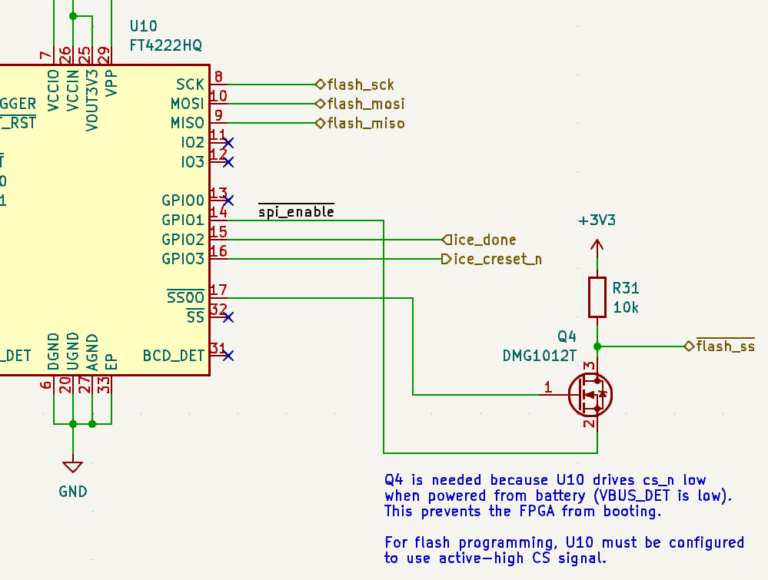
I simply needed to remember that the GPIO pin must be pulled low to enable control of the SS signal, but this inversion is easily managed within the FT4222 API during the programming sequence.
This experience highlights a key lesson in embedded development: never trust a control line to be idle when an external device is powered down—always consider the off-state behavior, especially for critical boot signals like SPI_SS. Happy debugging!